© Jean M Dean
WHAT IS RAW DATA AND WHY DO WE CARE? Print
This post relates to DSLR's although it is applicable (in the main) to astro-one shot colour cameras. We hear a lot about how we must use camera RAW and not JPEG. Why is that, and is camera RAW (.CR2, .NEF) actually raw?
In short you can stack JPEGs and it will give much better result than a single JPEG as it reduces some of the random shot noise in the images. For someone beginning their journey in AP stacking JPEGs is a good place to start, as it is relatively straightforward. But ultimately RAW is much better.
The raw files recorded by DSLR's are essentially raw. But not all software treats them in the same way. Let me explain starting with the sensor itself.
A DSLR sensor is made up of several layers, at the base is a semi-conducting substrate with photo-diodes. These collect photons which get converted into a voltage and later a digital greyscale value on a pixel within an image. Some people liken the photo-diode to a bucket and the photons to rain drops. The more rain drops in the bucket, the lighter the resulting pixel will be. If there are no raindrops the pixel is black, if the bucket overflows with rainwater then the pixel is saturated and white.
Above the photo-diodes sits a grid of coloured filters. This is called a colour filter array (CFA). It can also be called a “bayer matrix”. Strictly speaking this refers to the actual pattern, the one in the image is a bayer pattern as it contains repeating blocks of 4 colours where one is red, one is blue and two are green. This is the most common type used in DSLR’s, but there are other configurations.
Above this sits micro-lenses, and various other filters. But for this presentation we are not bothered about these layers.

So what is RAW?
This might look familiar to some of you. A Canon .CR2 raw file has been opened in Adobe Photoshop (PS), which opens up the Camera Raw application. You might have similar software supplied with your camera (such as Canon’s Digital Photo Professional).
This is not RAW; in fact it is a near finished image!
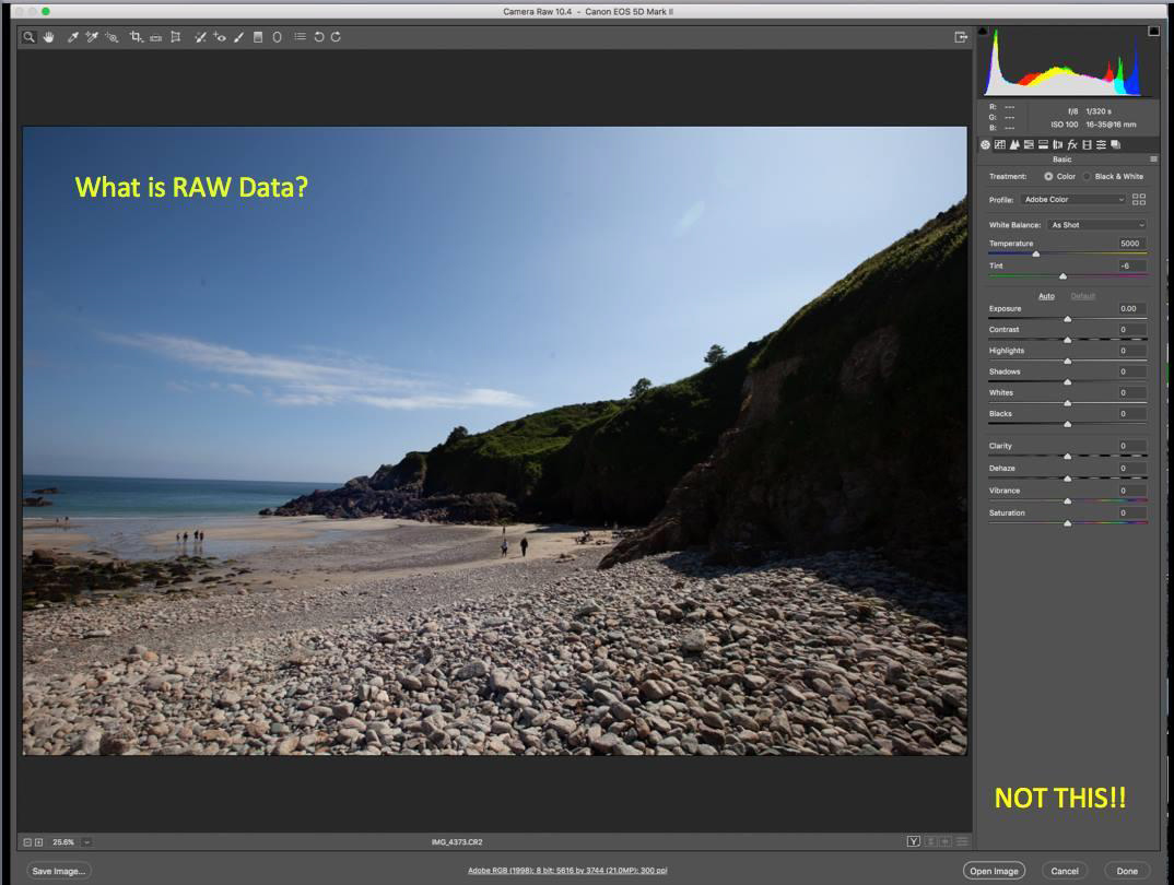
Let us start at the beginning of the whole process of creating a finished image, much like the one above.
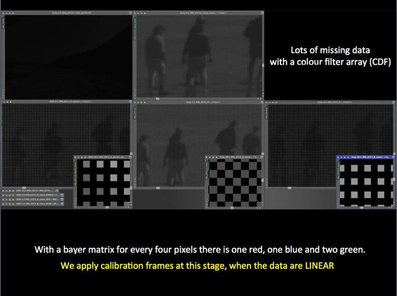
This is RAW. The top left image (yes the black one!) is the raw image. You might see why DSLR manufacturers don’t actually display the raw image, if the rear view screen showed this they would get a lot of returned cameras!!

The histogram shows all the data bunched up at the left hand side. For astro-images it would be even more bunched up. This is why I have chosen a normal scene, as it is much brighter and easier for this demonstration.
The top right image shows what is recorded. I have done a SCREEN STRETCH. This is an important term. I have stretched the image on my computers display, but I have not altered the actual data in the raw file. As astro-photographers (AP’s) we need to be able to work on the raw data. If we can’t see the effect of what we are doing then it makes it impossible to gauge if we are doing it correctly. So we stretch the image on the screen so we can see how we are doing.
The three bottom pictures are the images produced by the red, green and blue filters from the CFA. These are referred to as red, green and blue channels.
You might ask why are they mono and not colour? The camera does not really record colour, the coloured filter will filter specific wavelengths (in this case red, green and blue) but what is really being recorded is the luminance or intensity of the light getting through the filter so it is monochrome. Colour is added later.
Let’s look in more detail at the red, green and blue monochrome images:
The top image is the combined RGB. The lower three are the RGB channels. They look somewhat “blocky”. If we zoom in further then we can see missing data. In the red channel there is one grey block for every three black and same with the blue channel. On the green channel there are two grey blocks and two black blocks. This corresponds to the Bayer Filter Array where there is one red, one blue and two green filters in every block of 4. So each channel has missing data.
Why do we really care about all of this?
Because THIS IS WHEN WE APPLY CALIBRATION FAMES for the removal of electronically generated noise and vignetting. We cannot do it after this point and astrophotography specific software is required to do the calibration.
The data at this stage are LINEAR. The relationship between all the pixels is faithful, it is as recorded by the sensor. Understanding the difference between linear and NON-LINEAR is important, as we will see later. So what do we do about that missing data?
We estimate the values for it. It’s as simple as that. This is called DEMOSAICING (or in this instance DEBAYERING). There are several formulae for doing this, but the most common and successful way is to use an algorithm called VNG. It looks at the gradients between like coloured pixels and estimates the values that the blank pixels should have and gives them that value.

The three images at the bottom show a much smoother image now the blank pixels have been filled in (compare it to the previous slide).
The next step is to add colour and this is done in two steps. First red, green and blue are added to the appropriate channels. The proportion of colour added to each coloured pixel depends on the luminosity value of the individual pixel.
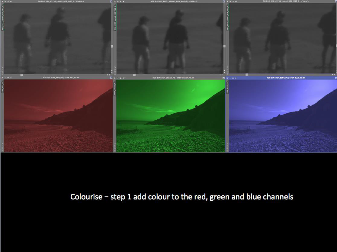
Now each pixel has a colour value for red, green and blue.
The second step is to combine these to produce a full colour image.
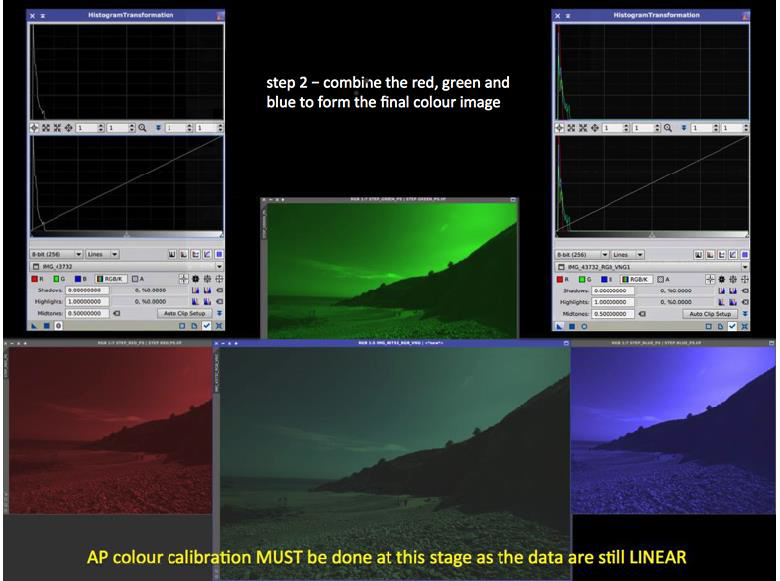
Now comes a very important point:
The data are still linear and it is at this stage we MUST do the COLOUR CALIBRATION.
Later we can make tiny changes and tweaks.
You will notice when combined there is an overall green tinge (bottom centre image) this is because camera sensors are designed to mimic human eyesight, which is most sensitive in the green wavelengths. This is unfortunate for AP as green is not really that common in space.
As DSLR’s are not designed for AP they struggle with the colour calibration. This is why astro-photography software works much better. Of course we can't actually see our targets in colour for real, so to get an accurate RGB colour calibration there are a few approaches.
One method uses the assumption that there are roughly an equal number of different coloured stars and their sum should equal white, another assumes that a typical spiral galaxy emits broadband light and can be used as the white point. A more accurate method can look at the known spectral response of individual stars, the best being a G2V star (our sun), which is used as the white point.
For normal AP any of the above methods work well. Most AP software has an “auto colour calibrate” option and most of the time this does a good job. If any green tinge persists after colour calibration then the level of green can be capped a little. But in the main automatic options typically work very well.
While the data are still linear we might want to do other things like some noise reduction but essentially the next step is to finally start stretching our data.
At this point our data become NON-LINEAR.
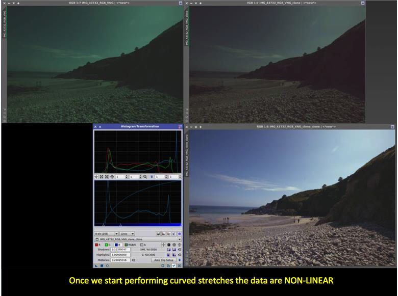
Top left is the colourised image, top right is the colour balanced and stretched image. AP software has specific stretching algorithms and methods. They are designed to stretch fainter regions such as dim nebulosity while not overstretching the brighter areas such as the cores of galaxies and areas of nebulosity that are brightly illuminated by stars.
One method is DDP (digital development processing). Strictly speaking this is not specific to AP, it was designed to simulate the human eye dynamic range. We are very good at seeing detail in shady and bright areas both at the same time. AP software that uses the DDP algorithm allows the user to vary the parameters to suit the astro-image. It is a very powerful approach. There are other techniques used such as Masked Stretching in Pixinsight, which is very effective.
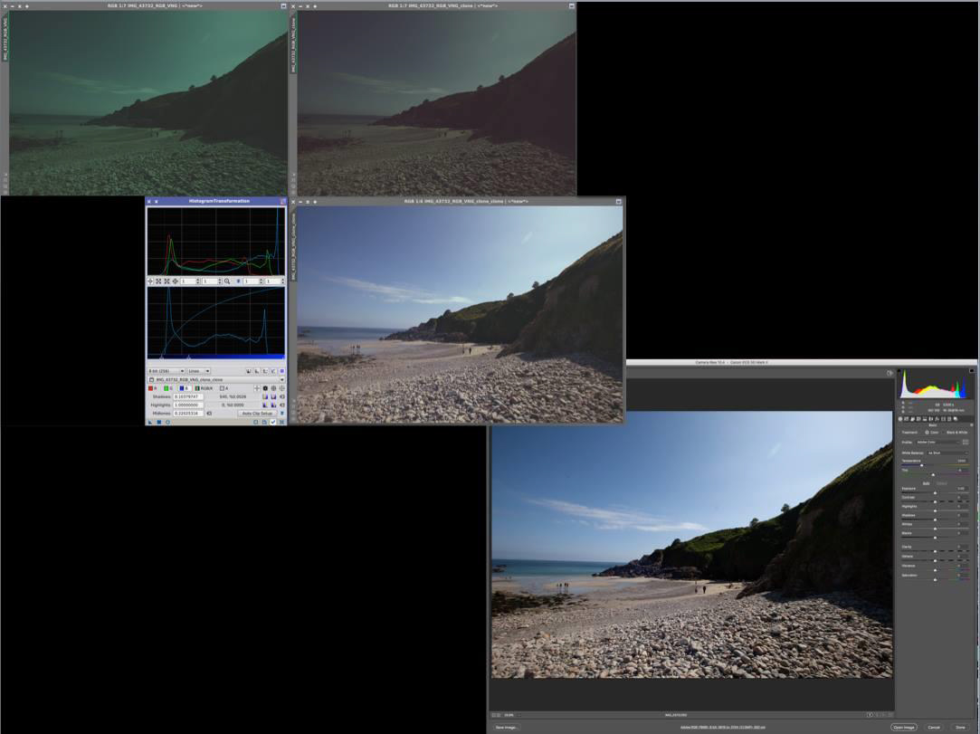
Complex stretches are in the main used first and once only for the initial stretch. Then all that is required is a series of smaller stretches, either in the combined RGB, but also in the individual RGB channels. The bottom right image is the result of 8 small stretches adjusting the brightness in the individual RGB channels to get the final balance. Of course in this instance I could see what was photographing and I had a good idea of what the photograph should look like! The histogram represents the final image.
We have now come full circle with this topic, if we look at the original RAW file opened in Adobe PS then we can see it is very similar to my final version processed from the genuine raw data.
Before you worry about how to do all this, astrophotography software does all of the above in just a few clicks without too much user input. That is why it is such a good investment, while Photoshop is really good for the final touches in an image and for creating masks.
You should take away from this:
Understand when CALIBRATION should be done and when COLOUR BALANCING should be done.
Appreciate what LINER and NON-LINEAR DATA mean.